Fiber cable for premises applications comes in many varieties of construction. When terminating or splicing these cables, the cable ends must be prepared to provide access to the fiber. Needless to say, fiber cable termination and splicing is a rather vital part of the whole cable installation process. This article will offer you a reference guide to delivery smooth and efficient fiber splicing and termination.
Fiber Cable Termination
Let’s start by illustrating various methodologies for optical fiber termination. Each has benefits and drawbacks, including the skill level required. Most methods are available for all connector styles. As with other connectivity components, procedures are rather component specific. Installers should refer to the applicable procedures.
NOTE: Bear in mind that there is a difference in the tolerance between single-mode fibers (SMF) and multimode fibers (MMF) mechanical connectors. You may use SMF connectors on MMF, but you may not use MMF connectors on SMF.
Pigtail Splicing: This method involves splicing a factory-made assembly onto the end of the cable. The assembly consists of a short piece of cable, pre-terminated on one end with the connector of choice. The advantage is that the connectors are pre-installed. The non-terminated end is spliced (typically fusion) to the cable.
No Polish Connectors: It is similar to pigtail splicing, minus the short piece of cable and using a mechanical splice rather than fusion. The connector actually contains a mechanical splice designed to mate with the fiber of the installed cable. The advantage is that the connector end face does not require field polishing.
Heat-Cured Termination: This method utilizes a heat-cured epoxy to secure the connector to the cable end. The installed fiber terminates at the connector end face and must be field polished.
Crimp Termination: This one utilizes a
mechanical crimp or compression to secure the connector to the cable end. The installed fiber terminates at the connector end face and must be field polished.
Guide for Fiber Cable Termination
Following are the steps for terminating fiber cables:
Step One: Verify that the correct termination components have been selected, compatible with both the fiber and the connecting hardware.
Step Two: Arrange the wiring scheme and organize cable by destination (rack, panel, etc.). If desired, optical fiber cable may be dressed or combed for a neat appearance
Step Three: Trim the cable length to reach the termination point without putting the cable under stress or violating the bend radius. Be sure to maintain cable identification.
Step Four: Follow the connectivity hardware manufacturer’s instructions for installing the termination hardware/connectors.
- Beware of anything crushing or excessively bending fibers or tubes.
- Properly bond and ground any cables with metallic components.
- If using a pigtail, protect all splices with a splice sleeve and suitable splice enclosure.
Step Five: Loosely bundle all exposed cable, preferably with hook-and-loop style straps.
Step Six: Clear out the work area.
Fiber Cable Splicing
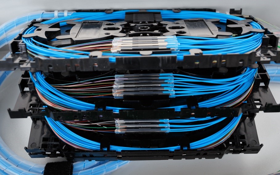
In general, splices are best avoided. And it often can be avoided due to the relatively short distances typical of premises networks. If splices are required, fusion splices (see details here) are recommended due to lower attenuation. However, mechanical splices are allowed. All fusion splices should be protected by a splice sleeve. All splices should be housed in a splice tray. All outdoor splices should be stored in an environmentally suitable splice closure.
Although there are common standards to ensure interoperability between cable and hardware, many hardware features are manufacturer specific. Therefore, the following steps should be used in conjunction with the instructions/guidelines relevant to the fiber splicing solution being employed.
Steps of Fiber Splicing
Step One: Verify that the correct fiber splicing method has been chosen, making sure that the tools and hardware facilitate the method to be used. There are some factors to consider when calculating splice and closure size.
- Cable construction
- Cable fiber count
- Splice type
- Splice location
Step Two: The space needs of the splice closure, the working space, and the cable pathway leading to the splice are important factors that need to be considered. The cable should not be bent so that it twists or violates the minimum bend radius.
Step Three: Use safety precautions to set up the splicing area using ladders or scaffolding, where required.
Step Four: Install a support structure for the splice if necessary. Sustain the proper bending radius of the cable, and keep room for the appropriate splice closure.
Step Five: Install the closure as the closure manufacturer’s instructions, and perform the splice with the splice/splicer manufacturer’s instructions, including but not limited to the following:
- Cable preparation – often the cable manufacturer’s guidelines and closure manufacturer’s guidelines must both be referenced to achieve the proper procedures and measurements.
- Secure all cables to prevent movement relative to the closure.
- Properly bond and ground any cables with metallic components.
- Provide sufficient fiber length inside the closure. Consider both current access and possible future changes. Balance fiber length on both sides of the splice to aid in neat fiber storage.
- Protect all splices with a splice sleeve and store all splices and slack fiber in a splice tray.
- Label the splice per the customer specification and update as-built drawings as necessary.
Step Six: Clear out the work area.
Conclusion
The process of fiber splicing and termination can be more complex in real-case practice. The guide for fiber splicing and termination offered in the article is considered feasible and convenient. I hope you could benefit from this.